Technical information about SMD
SMD - surface-mounted devices
Mentor, specialists in the development and supply of highly innovative precision industrial electronic components, backed by many decades of experience in this field, present in this catalogue one of the most extensive ranges of SMD products worldwide.
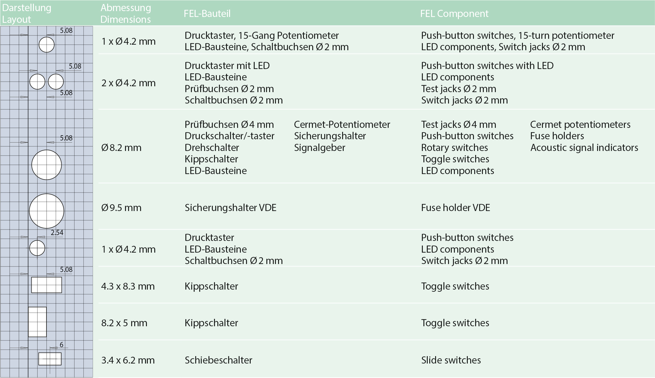
In addition to a complete system, based on the front panel installation parts according to DIN 41494, part 8 (inch system), display and control elements for SM technology use, Mentor offers an extensive range of individual SMD components. A side-by-side arrangement of more than three components has to be checked on a case-by-case basis and is possible on request.
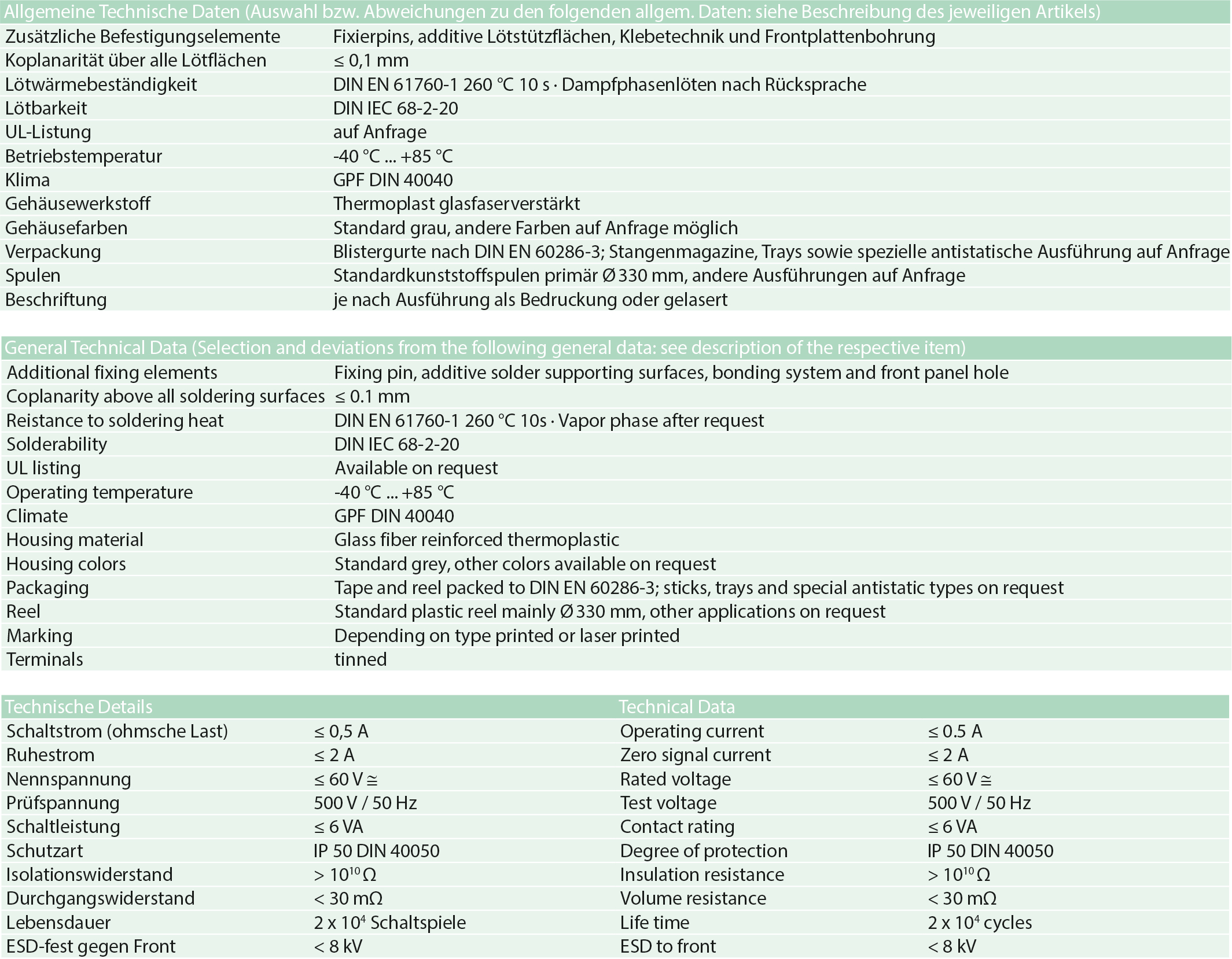
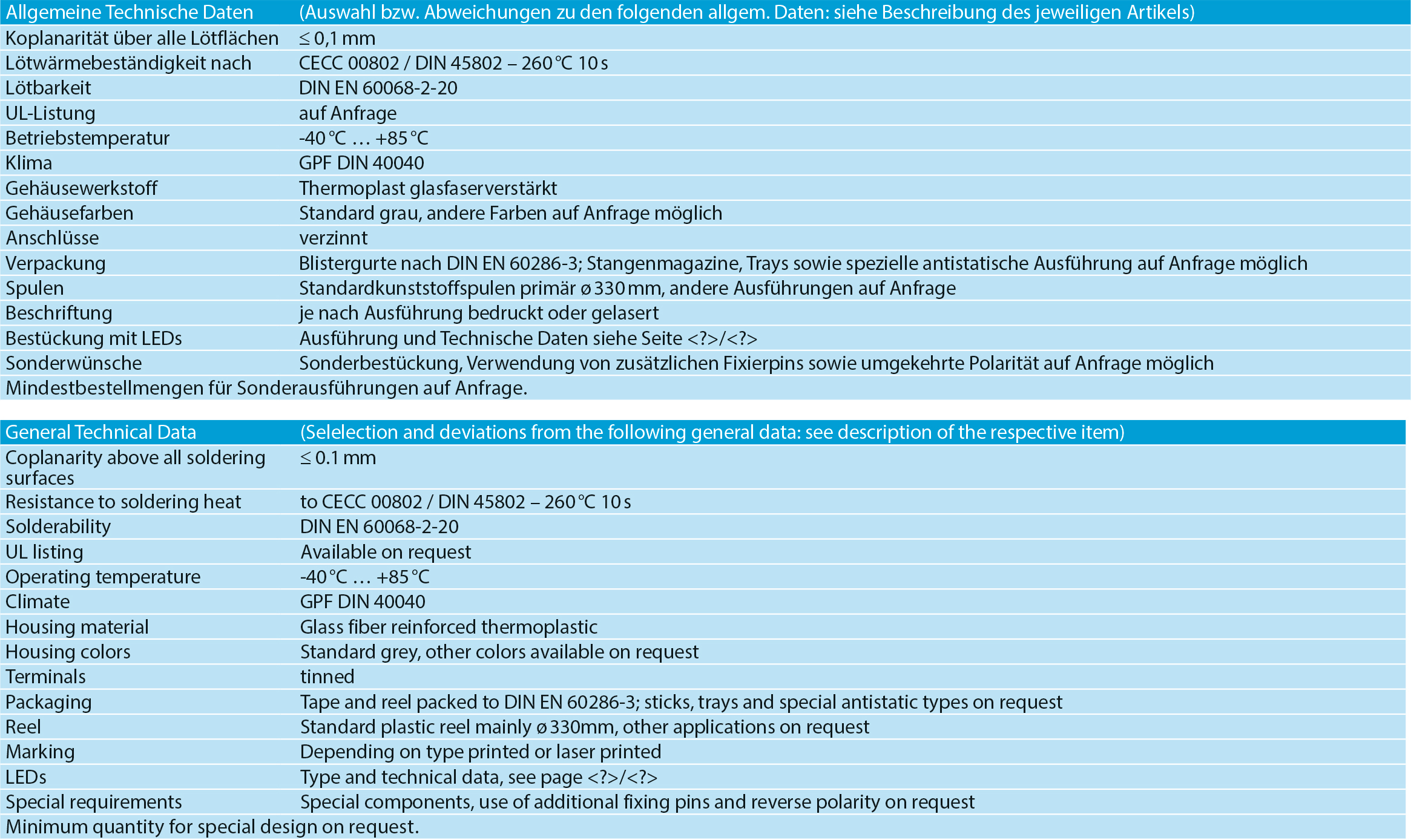
This component diversity offers design engineers the benefits of consistent printed circuit board design in SM technology. This consistency continues in the resultant placement and soldering techniques which make costly mixed placement unnecessary. It goes without saying that, in terms of thermostability, auto-placeability, coplanarity, blister packing, etc., the components comply with the technological requirements of our potential customers as well as with the relevant DIN standards.
We meet the constantly changing requirements of our customers with our wealth of expertise and innovativeness, which enable us to not only provide standard solutions, but also meet special customer requirements.
Please do not hesitate to contact us if you have any questions or specific requests. Our qualified sales staff and field force will be pleased to advise you. Special projects and/or special applications can be processed on request.
SMD switch systems
The Mentor switch series is based on the same concept as the designs that have been tried and tested millions of times through their widespread use in industrial electronics. As they have been further developed to meet the special requirements of SM technology, they are now available for the changeover to the placement of SMDs. An important aspect was to use gull wings as the connection type, as it is the most widely used type due to its many advantages such as reproducible grid dimensions, self-centring features, improved shadowing problematic, good visual soldered joint inspection and easy resoldering and unsoldering.
SMD-LED display systems
Mentor’s many decades of expertise as developer and supplier of industrial electronic components have influenced the development of these surface-mounted devices.
Their design is based on extensive studies, some of which were carried out in the context of a research project.
The SMDs are available as single and dual LED components in various dimensions, depending on their intended application.
An important aspect of the design was to use gull wings as the connection type, as this is the most widely used type due to its many advantages such as reproducible grid dimensions, self-centring features, improved shadowing problematic, good visual soldered joint inspection and easy resoldering and unsoldering.
Technical information about FEL
Standardisation of slide-in technology
The sizes of printed circuit boards and frame plates, the rack dimensions and the front panels with their dimensions are all standardised in DIN 41494. Sheet 4 of DIN 41494 is specifically about the rear connections for PCBs.
The key dimensions of the installation space for front panel installation parts are already determined by the PCB and front panel dimensions defined in DIN 41494 T. 2 and T. 5 and the component placement grid defined in DIN EN 60097.
At the same time, the packing density on the printed circuit boards increases with the use of integrated circuitry. The customary method of mounting display and control elements on the front panel and then connecting them to the PCB through conventional wiring was not consistent with the overall concept of “electronic equipment” designs as it required too much effort and did not allow for sufficient packing density of the control function. It was therefore not a satisfactory solution. These disadvantages were found to be even greater with the increasing popularity of flat assembly units as opposed to compact ones, reducing the space for the front panel to a minimum. The following requirements had to be met in order to find a practical front panel control solution: Minimum dimensions, modular housing design to achieve high packing density and easy assembly to avoid the manual wiring of individual elements. All these requirements are met by the FEL (short for “front panel installation parts on PCBs”) system.
The installation conditions for the “front panel installation parts” currently used in the 19-inch assembly system are defined in DIN 41494 part 8. The term “front panel installation parts” covers both display and control elements.